CIP cleaning: designing an in-place sanitation system
How to design a line for clean-in-place sanitation: radii, slopes, drainage, temperature and solution flow speed. A practical engineering breakdown.
CIP (Clean-in-Place) is the cleaning of equipment without disassembly, where the cleaning solution circulates inside pipework, tanks and conveyors. A well-designed CIP system saves hours of sanitation every shift and guarantees a repeatable result. In this article we look at how to build CIP capability into a line at the design stage.
How CIP works
A CIP cycle is a sequence of phases, each with its own temperature and duration. The solution is pumped through all contact surfaces and returns to the station where it is filtered and reheated. A classic cycle has five phases:
- Pre-rinse with cold or warm water — removing the bulk of product residue.
- Alkaline phase — circulating a 1–2% NaOH solution at +70…+85 °C, breaking down fats and proteins.
- Intermediate rinse with clean water.
- Acid phase — a 0.5–1% nitric or phosphoric acid solution, removing mineral deposits.
- Final rinse with potable water to neutral pH.
For this sequence to work, the equipment must be designed for solution circulation, not just for transporting product.
The effectiveness of any CIP phase is described by the classic “Sinner circle”: the cleaning result depends on four factors — chemistry, temperature, mechanical action and time. One of them can be reduced only by compensating with another. For example, if you lower the temperature, you have to extend the cycle or raise the solution concentration. A competent CIP design is not the maximisation of all four factors but their balanced combination for the specific type of soil.
Four rules for designing for CIP
CIP capability is built into the geometry. On our projects we follow four basic principles:
- Self-drainage. All surfaces have a slope of at least 3° toward a drain point — solution must not pool.
- Minimum radii. Internal corners are at least R3, and in zones of direct product contact R6, so the jet reaches every point.
- No dead ends. No blind branches, static threads or pockets where the solution is not refreshed.
- Turbulent flow. Solution speed in the pipework is at least 1.5 m/s, otherwise cleaning relies only on chemistry, not on mechanical removal of soil.
Breaking any one of these rules turns CIP into a formality: the solution circulates but the dead zones stay dirty.
Temperature and hydraulic parameters
CIP effectiveness depends on a combination of four factors: temperature, chemical concentration, time and the mechanical action of flow. Below are the typical regimes we build into a vegetable washing line project.
| Cycle phase | Temperature | Duration | Flow speed |
|---|---|---|---|
| Pre-rinse | +20…+40 °C | 3–5 min | 1.5 m/s |
| Alkaline phase | +75…+85 °C | 10–20 min | 1.8–2.1 m/s |
| Intermediate rinse | +20…+40 °C | 3–5 min | 1.5 m/s |
| Acid phase | +60…+70 °C | 8–15 min | 1.8–2.1 m/s |
| Final rinse | +20 °C | 5 min | 1.5 m/s |
Engineer’s tip. Build sight glasses or swab points at the end of each CIP loop. Without them you cannot see cleaning quality or take a rinse-water sample for laboratory control.
Conveyors in a CIP system
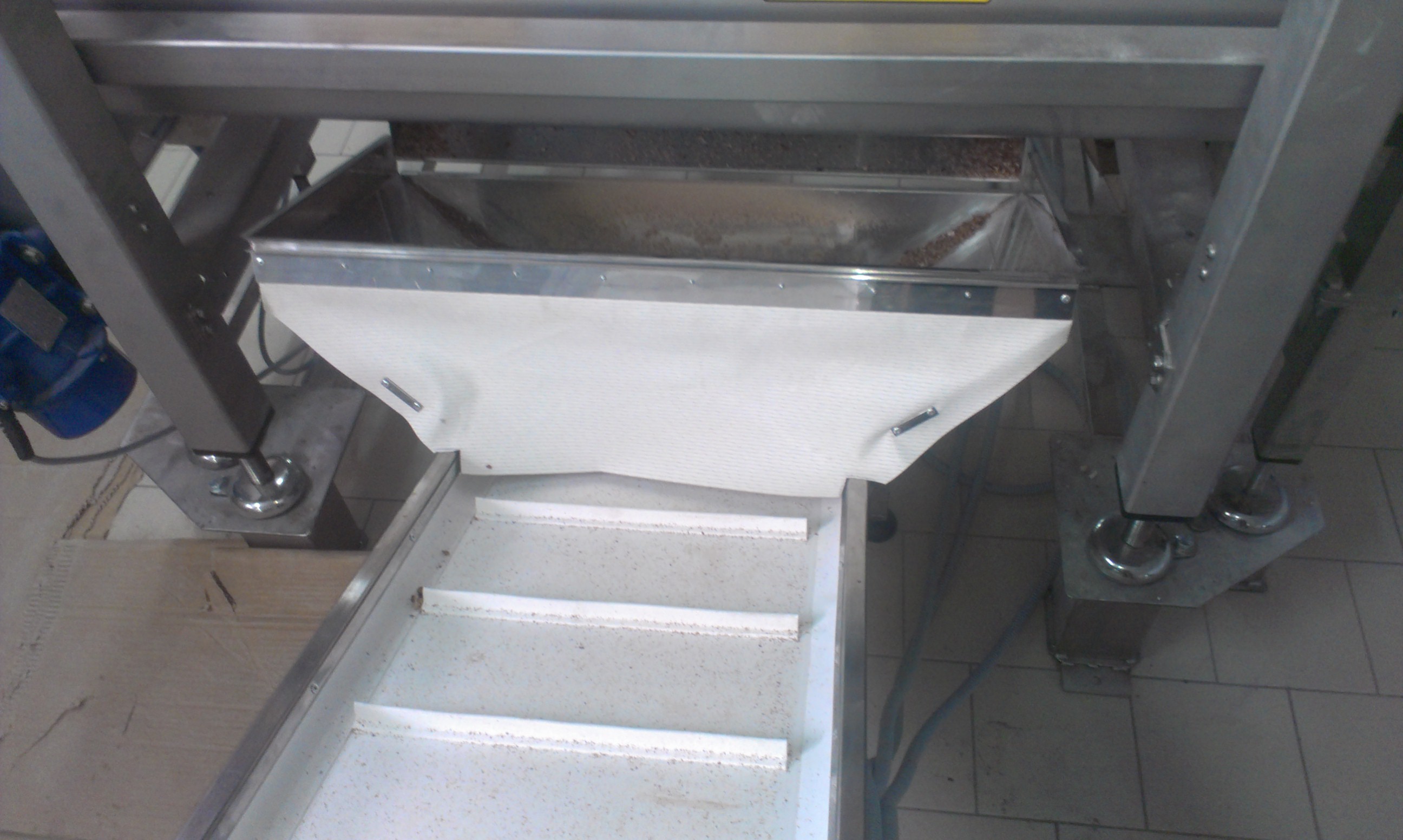
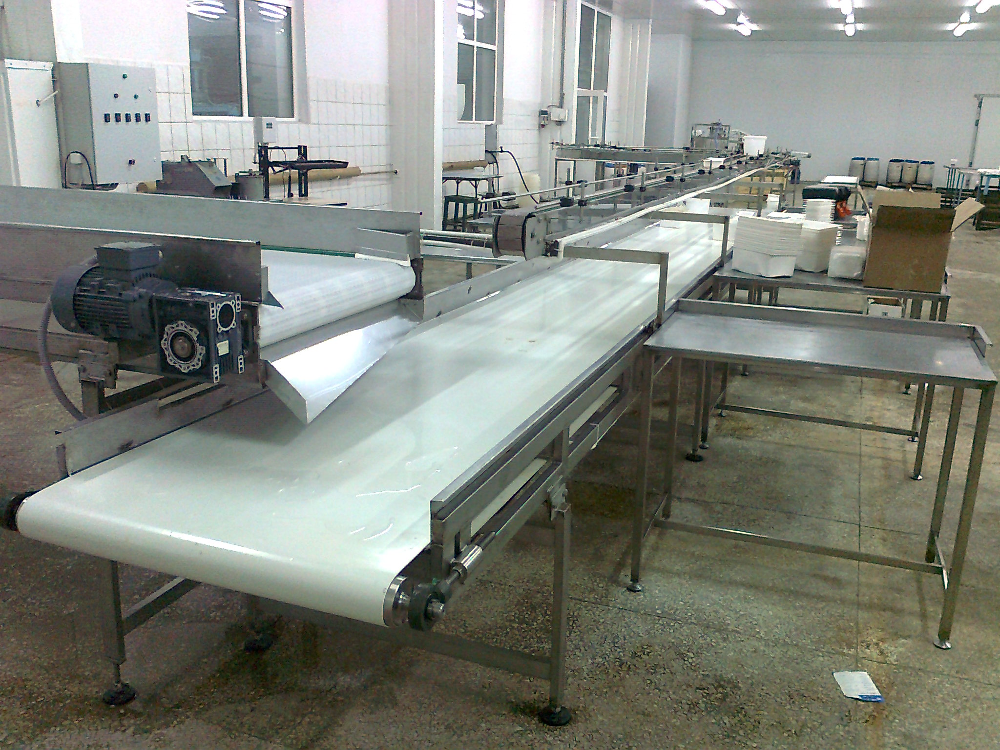
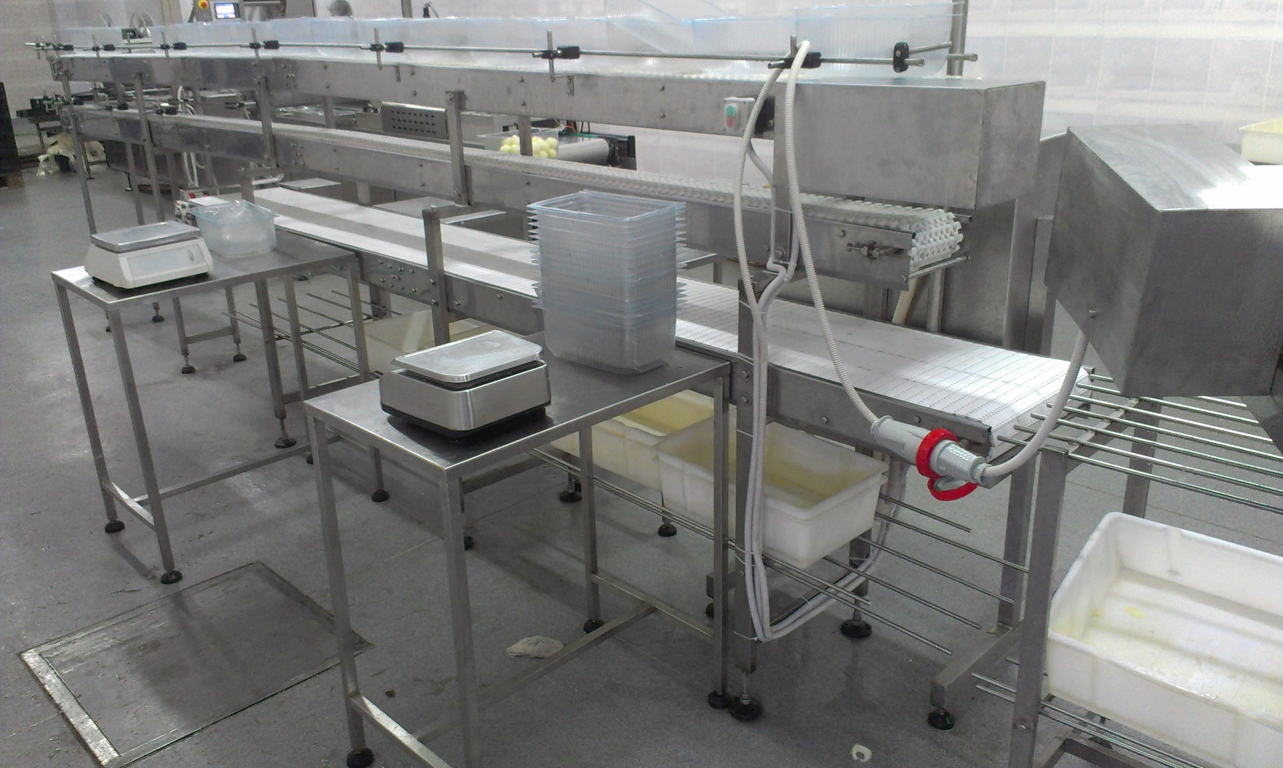
A conveyor in the CIP zone is a separate challenge. A solid belt cannot be fully cleaned on the inside, so in wet zones we install modular belt conveyors: the open-structure mat is rinsed by jet from all sides. Drive drums and tension units are moved outside the product-contact zone or made removable for manual touch-up.
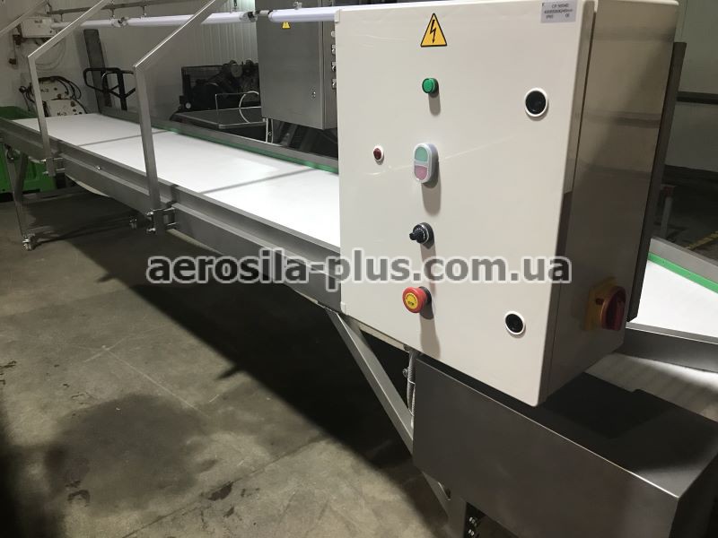
The conveyor frame in a CIP line is AISI 304 stainless steel with closed profiles and no holes for water to collect. All electrical components are IP65-rated and above, because CIP involves pressure washing.
A CIP system saves more than staff time. Clean-in-place gives a repeatable, documented result: every cycle runs to the same parameters, which are recorded automatically. This is fundamental for an HACCP audit — the auditor sees not “the line was washed” but specific records of temperatures and times for each phase. Manual washing, by contrast, depends on the person and hardly lends itself to objective control.
The spray-head system is designed separately. For open surfaces and tanks, static or rotary spray balls are used to distribute the solution in an even fan. Head placement is calculated so the fans overlap and leave no “shadow” zones behind structural elements. The number and capacity of the heads are directly linked to the CIP station pump power: an undersized pump will not deliver the required flow speed, and the whole turbulence calculation loses its meaning.
Conclusion
CIP is not a separate apparatus but a property of the whole line, set at the sketch stage. Self-drainage, minimum radii, turbulent flow and no dead ends — these distinguish a line that can genuinely be cleaned from a line that is only formally rinsed. Designing a new washing line or adapting an existing one for CIP? Get in touch — we’ll calculate the loops and regimes. More on sanitation under the tag hygiene.