Stationary bunker: volume calculation and design
How to correctly calculate the volume of a stationary bunker for bulk or unit loads and choose the wall and outlet design.
A stationary bunker is a storage vessel that smooths out feed irregularity between line operations. An error in calculating the volume or wall angle leads to product bridging or frequent overflows. Let’s break down how to design a bunker correctly.
Why a storage bunker is needed
A bunker acts as a buffer: it receives product from the previous operation and feeds it onward in an even flow. This allows line sections to run at different throughputs without stopping each other. A stationary bunker is mounted rigidly on a frame or floor — unlike a mobile one.
A buffer is needed in two typical situations. The first is when the previous operation runs cyclically (for example, unloading a tipper truck) and the next one runs continuously. The second is when the throughputs of adjacent sections do not match, and the slower operation has to “catch up” using the accumulated reserve. Without a bunker the line runs in fits and starts: it either idles waiting for raw material or chokes. A correctly sized volume smooths out these fluctuations and keeps the line tempo stable.
Working volume calculation
The working volume is determined by the required autonomous operation time. The basic formula:
V = (Q × t) / (ρ × k)
where Q is line throughput (t/h), t is the required time reserve (h), ρ is the bulk density of the product (t/m³), k is the fill factor 0.8–0.9.
The time reserve t is determined by the bunker’s purpose. To smooth out minor feed fluctuations, 10–20 minutes of autonomous operation is enough. If the bunker has to cover a stop of the previous operation — for example, a container change or a raw-material loading pause — 1–2 hours are allowed. The fill factor k accounts for the fact that a bunker is never filled to the brim: a free volume is needed above the product for the angle of repose and for level fluctuations. To the calculated volume, the conical outlet section is added, which also holds product.
Engineer’s tip. Always calculate the volume by bulk, not true, product density. For grain the difference reaches 40%, and a bunker calculated “from the substance reference” turns out too small.
Product hold-up: bridging and ratholing
The two main problems of a bunker for bulk product are bridging and ratholing. Bridging occurs when product particles above the outlet wedge against each other and form an arch that holds the weight of the whole column above it. The product does not discharge, even though the bunker is full. Ratholing (a central funnel flow) is when only a narrow column above the outlet discharges, while the product along the walls stays motionless and cakes. Both problems are solved by geometry: a sufficiently steep wall angle, a smooth inner surface and the correct outlet diameter. For difficult products, flow activators are added — a wall vibrator, an aerator or an agitator.
Wall angle and outlet
To prevent product bridging, the cone wall angle must exceed the material’s angle of repose. Below are approximate values.
| Product | Bulk density, t/m³ | Angle of repose | Min. wall angle |
|---|---|---|---|
| Wheat grain | 0.75 | 25° | 35° |
| Granulated sugar | 0.85 | 35° | 45° |
| Flour | 0.55 | 45° | 55–60° |
| Polymer pellets | 0.60 | 30° | 40° |
For problematic, caking-prone products the walls are made even steeper or a vibrating chute is added at the outlet.
Material and design
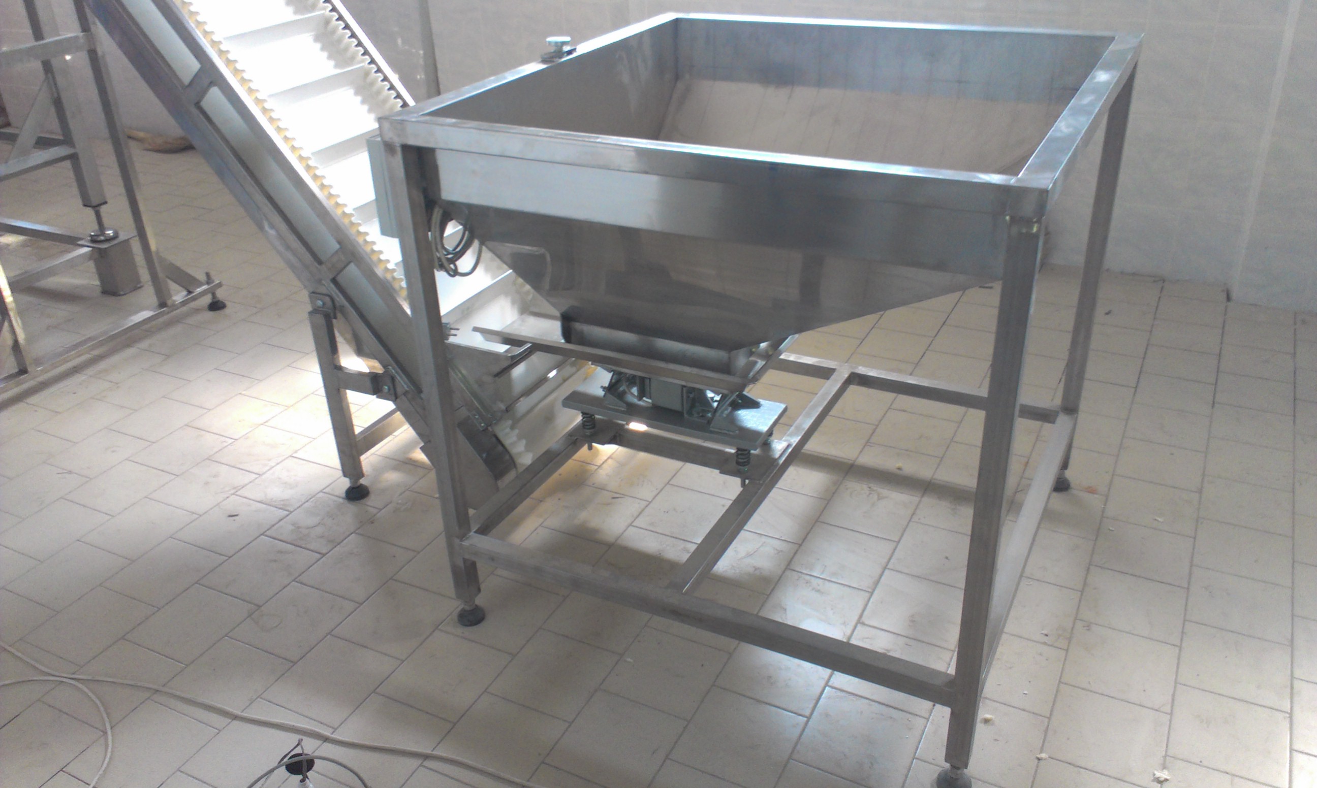
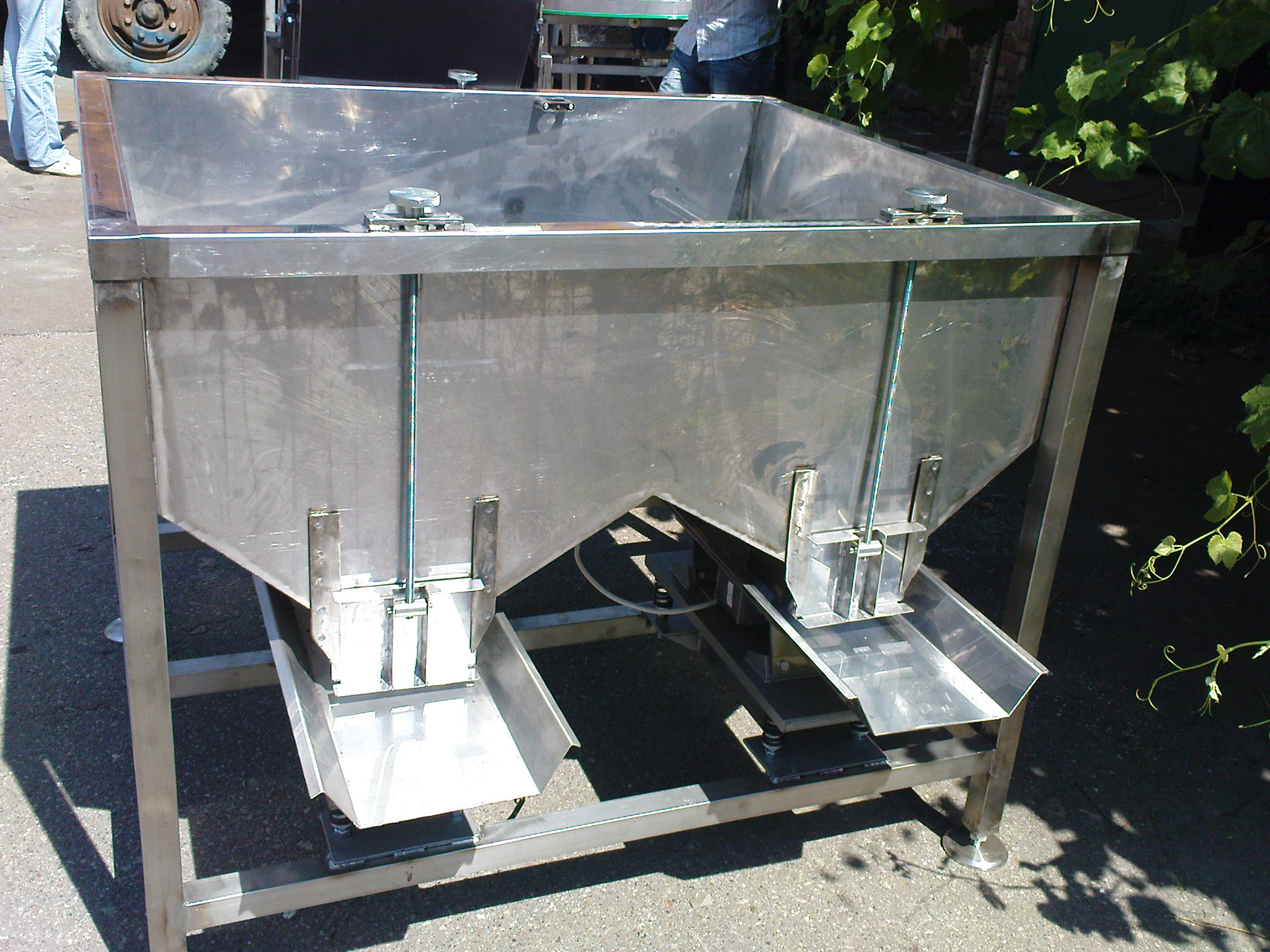
For food products the bunker is made of AISI 304 stainless steel with a polished inner surface — this reduces friction and eases cleaning. The wall smoothness works on two fronts at once: the lower the friction coefficient of the product against the steel, the more reliably the product moves down to the outlet and the less steep the cone can be. A polished surface also keeps product from sticking, which is critical for flour, icing sugar and other fine materials. The design includes:
- a loading neck with a grate;
- a cylindrical or prismatic body;
- an outlet cone with the required angle;
- a gate valve or vibrating dosing chute;
- level sensors (minimum and maximum).
The design choice depends on the product — more in the bunkers and vibrating chutes section.
Level sensors and outlet control
A stationary bunker rarely works “blind”. Level sensors make it part of the line automation. A minimum sensor at the bottom signals to start loading as soon as the reserve approaches critical, and a maximum sensor at the top stops the feed before overflow. A third, intermediate sensor is often placed between them for smoother control. By type, rotary (paddle) sensors are used for dry bulk product, capacitive ones for fine and sticky materials, and ultrasonic and radar ones for non-contact measurement in dusty environments. The outlet is controlled by a gate valve with a pneumatic or electric actuator, or by a vibrating dosing chute that also smooths the flow at the exit. A well-integrated bunker works without an operator, driven only by sensor signals.
Conclusion
The right bunker is a balance of volume, wall angle and outlet method for the specific product. The calculation takes an hour but saves the line from bridging and downtime. To design a stationary bunker for your throughput — get in touch.